|
Building and Surface Settlement marker
Building settlement marker is used to monitor the vertical settlement/ movement of any structure. Building settlement marker of stainless steel male and female threaded socket are embedded/ fixed to a column/ wall.
The surface settlement marker is used to monitor the vertical settlement or heaving of the ground surface. It consist a deep ground settlement point of steel rod installed into the ground with 0.02m above the ground surface.
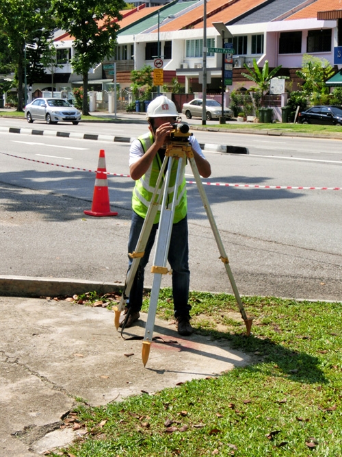
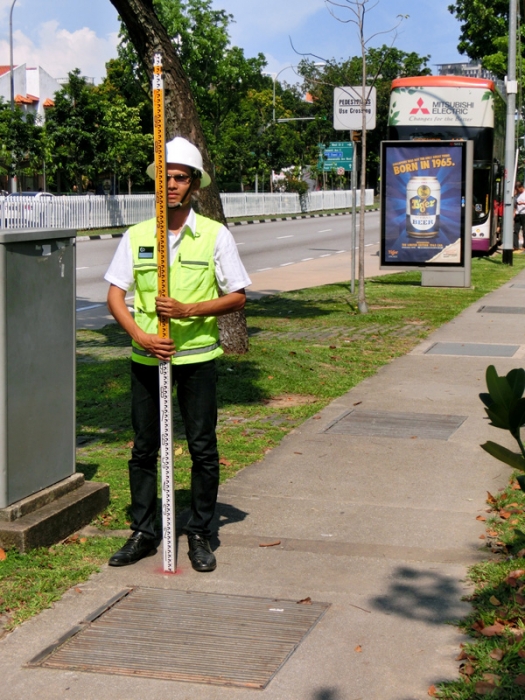
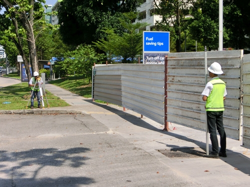
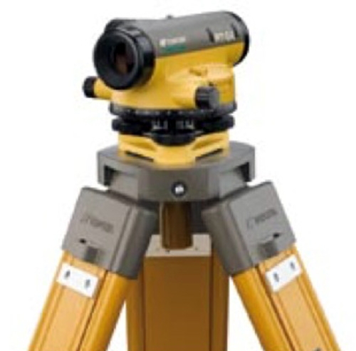
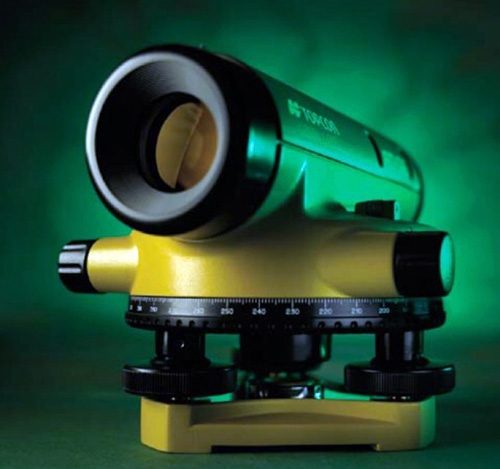
A total station or digital level equipment is used for the monitoring of these settlement points.
Crack meter Monitoring
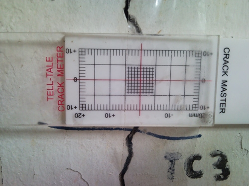
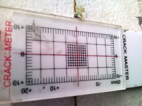
Crack meter is used to measure the movement of joints or cracks on vertical walls or slope. The standard crack meter or tell-tale is composed of two parts with scale graduated on the surface in millimetres. The scale of one part can slide on the scale of the other part. The crack meter is to be placed firmly by epoxy with the scale of reading perpendicular to the crack line at the chosen spot. The widening or closing of the joints or cracks will cause, on plate moves relative to the other. The relationship of the cursor to the scale represents the amount of movement occurring.
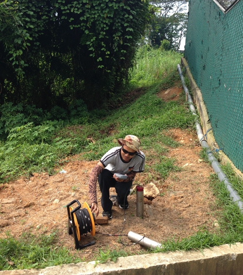
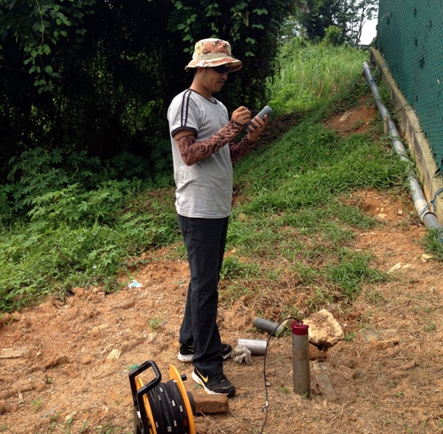
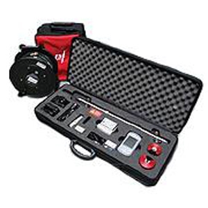
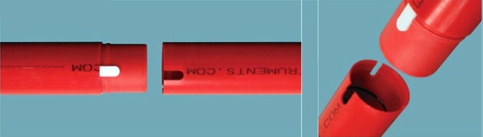
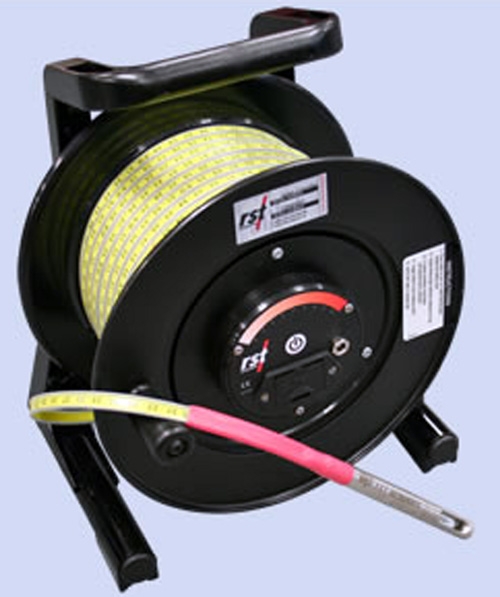
Inclinometer
The purpose is to evaluate the stability of slopes and embankments and determine the need and timing for corrective measures. The inclinometer casing is typically installed in a near vertical borehole that passes through suspected zones of movement into stable ground. The readout unit (Ultra-rugged Field PC running Microsoft WindowTM ), the inclinometer dummy probe, cable and reel of RST inclinometer system are used to record magnitude of ground movement or displacement at each depth.
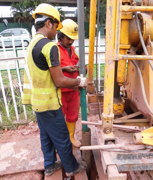
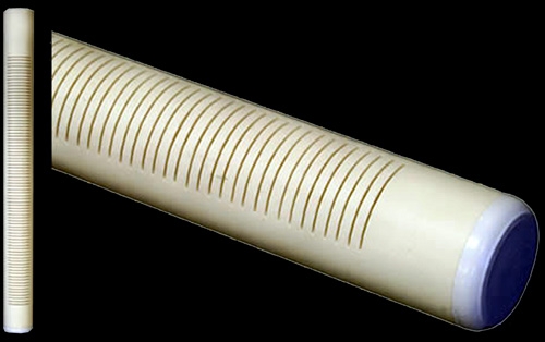
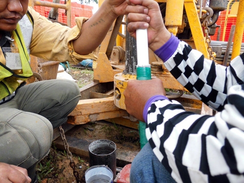
Water Standpipe
The purpose is to monitor ground water level during excavation and underground construction activities. It consists of a 50mmϕ rigid PVC pipe with perforation or slots over its lower end and wrapped with a layer of nylon mesh, completed with a PVC cap at the bottom, then installed in the completed borehole. RST hydrometer (Model 4301, Combo) is used to monitor the ground water level in the water standpipe.
Standpipe Piezometer
It is mainly used for measurement of piezometric levels and pore water pressure in soil and rock formations. It consists of a slotted PVS body that encloses and protects a porous plastic filter element. A PVC riser pipe is connected to the tip and extended to the surface. A hydrometer is used to monitor the ground water level in the standpipe piezometer.
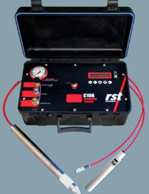
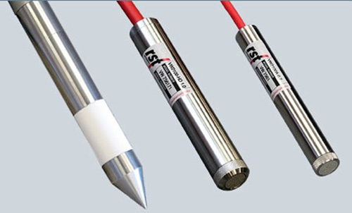
Pneumatic Piezometer
Pneumatic piezometer utilizes water and gas pressure to measure pore-water pressure. The piezometer is sealed in the borehole, and twin pneumatic tubes run from the piezometer to a terminal at the surface where readings are obtained with a pneumatic indicator.
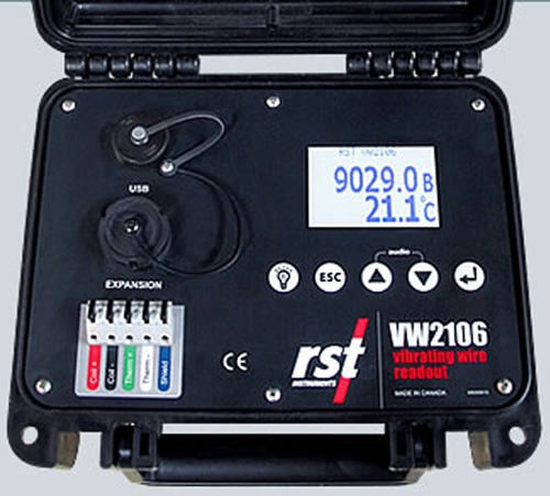
Vibrating Wire Piezometer
Vibrating wire piezometers allow for measurements of pore water pressure under the most adverse conditions. Vibrating wire piezometers have traditionally been installed in the same manner as pneumatic piezometers or standpipe piezometers. A sand intake zone is tremied around the piezometer and then sealed with bentonite. The remainder of the hole is then filled with a bentonite cement grout. The vibrating wire piezometers contain a high tensile steel wire a fixed anchor at one end and are attached to a diaphragm in contact with water pressure at the other end. The wire is electrically plucked, with the resonant frequency of vibration proportional to the tension in the wire. This frequency induces an alternating current in a coil which is detected by the readout unit, such as the VW2106 vibrating wire readout, and then be converted to a pressure.
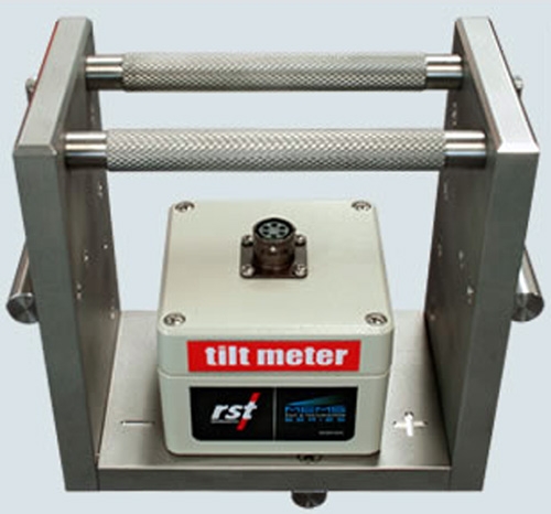
Tiltmeter
The objective is to monitor changes in the tilt of a structure due to nearby construction activities. The tilt plate is fixed into the wall by applying epoxy to the base of the tilt plate, after the surface of the wall is clean from dirt or spilling mint. A tilt readout unit Sinco type is used to record the angle of tilting of each of the tilt plate.
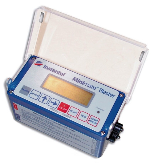
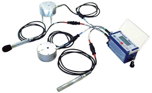
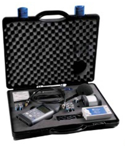
Vibration & Noise Monitoring
A vibration monitoring programme is carried out to monitor the ground vibration during construction works. The vibration meter is used to conduct the vibration monitoring. It is a microprocessor controlled seismic recorder capable of recording 300events memory during any vibration impact due to construction or other activities. The monitor measures transverse, vertical and longitudinal ground vibration. A calculated Peak Particle Velocity (PPV) versus the corresponding frequency and the resultant Peak Vector Sum (PVS) is presented complying with the German DIN 4150 specification.
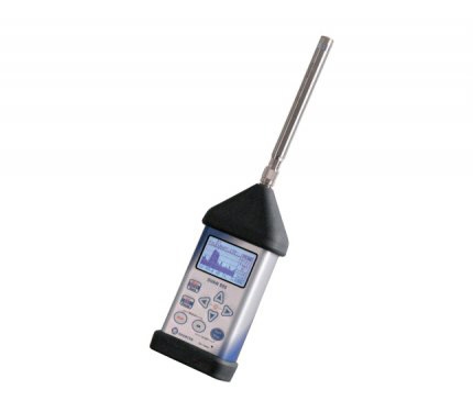
A noise monitoring is carried out to monitor the noise during construction or piling activities. A Type 1 sound level meter dedicated to environmental noise monitoring is used to conduct the noise monitoring. This unit is equipped with an advanced data logger enabling up to 12 results logged simultaneously from three independent profiles (Peak, Max, Min, RMS results from each profile) with step down to 2ms. To start the monitoring, a preamplifier with the microphone is plug into the equipment. The computational power of its digital signal processor can perform real time statistical calculations.
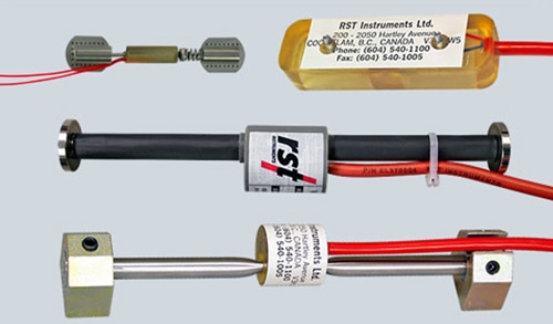
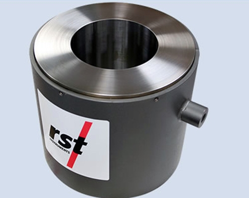
Strain gauges & vibrating wire load cells
They are used to proof-test and measure loads in tie-backs, rock bolts, ground anchors and struts. For strain gauge load cell monitoring, the steel surface is cleaned using wire brush to remove all scale, rust and oil. The blocks are then removed from the spacing and pressed firmly against the steel surface using spacer bar as a handle. The edges of the mounting blocks are now welded in the order. After welding cool the mounting blocks with a water soaked rad, then slacken the set screws and slide out the spacer bar. Clean away all welding slag using a chipping hammer and wire brush. The readout unit will display directly in microstation when connection to VWSG-A Strain Guages. Thus, the change of strain between the initial reading (R0) and nay subsequent reading (R1) can be calculated by simply subtracting the initial strain from the subsequent strain. The strain gauge reading obtained can be converted to the load/force in kN latter and the total changes can be calculated by compare the current reading with the initial reading. Similar to the resistance strain gauge load cells, with vibrating wire strain gauges attached to the cylinder instead of resistance gauges. Normally three gauges are attached at equal intervals around the cylinder. Sometimes the gauges are fitted in machined slots in the wall to minimize size of the entire cell.
|